19
Scaling Up from the Bench: Fermentation Tank
Victoria Lee
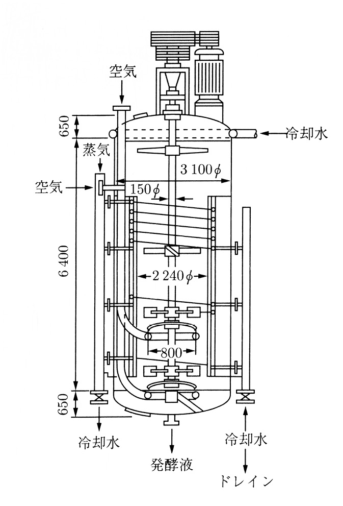
Fig. 19.1 50kl stirred aerated fermenter (source: Yoshida 2001: 491)
Name: fermentation tank. Other names: fermenter, reactor, bioreactor. Family: chemical industry. Size and shape: the common types of tank can range in size, containing up to hundreds of kilolitres. Cylindrical. Habitat: outdoors or indoors at factory sites in the food and pharmaceutical industries. Distribution in Japan: nationwide. Life cycle: begins with bench research and the construction of a smaller pilot tank, followed by the industrial-scale fermentation tank. Able to make a variety of products once in operation. Human connections: produces food and drink for human consumption, including beer, vinegar, liquors, and yeasts. Also makes non-food products, including solvents, enzymes, biofuels, organic acids, antibiotics, and recombinant protein products. Ecosystem connections: culture media rely significantly on raw materials that are available locally and in abundance. Microbial strains are maintained locally but have widely varying origins. Waste products (such as yeasts) may be put to other uses.
Keywords: fermenting (hakkō), culturing (baiyō), growing (hatsuiku), converting (tenkan), producing (seisan), controlling and regulating (chōsetsu), maintaining (hoji), distributing (bunpu), operating (sōsa), consuming (shōhi), scaling up (sukeeruappu), industrialising (kōgyōka)
A fermentation tank is most commonly represented in a schematic manner, as in the diagram in Figure 19.1. Fermentation tanks are physical objects that are made of hard materials such as steel. When in a tank’s presence, it is hard to miss. It is often much larger than people or buildings, and as the focal point of a production process it dominates spaces, whether it stands outdoors in the sun within a factory site, or under the glow of indoor laboratory lamps. Yet the details concerning how any one tank became a physical reality have commercial value and need to be safeguarded. Publications that give information on these tanks in the public domain tend to emphasise the general and not the specific. Few photographs of fermentation tanks are widely available, since such images are carefully regulated by the producers, which are frequently corporations. A universal diagram, therefore, is more representative than a photograph. Mirroring the way in which tanks separate, protect, and conceal their interior contents from their surroundings, specific facts on individual tanks are also isolated, protected, and concealed from the outside technical community.
The diagram in Figure 19.1 shows a fifty-kilolitre fermenter. A large-scale fermentation tank is a piece of industrial technology that cheaply mass-produces cells or goods from cells (for example, yeasts for bread and beer, alcohol, enzymes for detergents). It is a controlled space of conversion. The fermentation tank holds a culture medium that was created through a process of trial and error as the optimal, cost-efficient chemical environment to grow a particular microbial strain with available raw materials. The microbial strain was selected as the cell that has the ability to yield high amounts of a specific product in a short time. Together these make up the fermentation broth, which the tank isolates and insulates from the outside environment, keeping the inner environment artificially sterile and at a fixed temperature in order to maximise cell performance and, therefore, product yield. Inside some fermentation tanks, cells may perform an anaerobic fermentation process, and thus may not require an air supply, but in the tank depicted here, the process is aerobic and the cells need air to accomplish the reaction.
Sterilised air passes to the cells through the pipes depicted by the uppermost downward-pointing arrow as well as the rightward-pointing arrow on the left, which bring the air inside the tank. An agitator, which we can see attached to the vertical axis of the tank, stirs the fluid and breaks the air into bubbles that travel to the cells dispersed throughout the culture medium inside the tank. In order to keep the tank walls sterile, steam passes through the pipe that the leftmost downward-pointing arrow designates. An insulating jacket of cooled water – which we see flowing into the pipes shown by the leftward-pointing arrow on the top right and the upward-pointing arrow on the bottom right, and into drains on either side at the bottom of the tank – surrounds the tank and regulates its temperature. Collection of the fermentation broth takes place through the central pipe shown at the bottom of the tank. From the broth, the desired product will be extracted and refined elsewhere in the plant.
Before an existing industrial-scale fermentation tank can manufacture a new commercial product, such as a chemical, engineers must first ‘scale up’ the techniques used and preliminary data obtained when scientists culture strains and make chemicals at the laboratory bench. Only by a process of scale-up can engineers apply bench-scale techniques and data to industrial-level production. Scale-up takes place step by step, typically from shake flask to jar fermenter, to pilot plant, and to industrial tank. Much as the inputs and outputs of the tank contents must be measured and controlled, requiring supervision and surveillance at a distance, so the circulation of knowledge about fermentation and scale-up processes is also restricted. The components of a process must be designed in a way that does not violate existing patents. Many details of fermentation processes are commercial secrets or published only in patents. Similarly, details of scale-up methods are confidential information.
The type of tank about which there is the most information available to the public is the one depicted in the diagram in Figure 19.1: the stirred tank for aerobic fermentation. This type of tank first appeared in the late 1930s for yeast production, and scientists and engineers around the world researched the tank intensively in the immediate post-World War II period for mass-producing penicillin (made by a fungus). Since the end of the war, the stirred aerobic tank has predominated in the pharmaceutical industries, because the same tank can be used to produce any kind of antibiotic as well as many other cell metabolites made in aerobic conditions. We have numerous accounts of penicillin’s history, even though its manufacturing processes were also patented (the drug itself was not patented, for humanitarian reasons). Here I focus especially on Japanese accounts, and this essay is based on translations from Japanese papers. Penicillin histories help sketch out a brief pedigree of fermentation tanks and, more broadly, the ways in which fermentation tanks compelled scientists to reconcile bench results with real-world engineering problems.
Tank Pedigree
Across the world, people have used non-sterile or ‘open’ tanks in diverse brewing industries for many centuries. In the late nineteenth century, scientists developed techniques to isolate, preserve, and define individual microbial strains, which relied on culturing the strains ‘purely’ – propagating a single strain in an otherwise sterile environment. Scientists argued that beer brewers could lower the risk of spoilage, and industrial alcohol manufacturers could raise yields, by sealing off the environment and using pure cultures, creating ‘closed’ fermentation tanks. These new microbiological concepts and techniques affected fermentation technologies in many places, including in Japan. There are different kinds of fermentation and, accordingly, different kinds of tank. Industry specialists divide fermentative production into three kinds: anaerobic fermentation (does not require air), aerobic fermentation (requires air), and photosynthesis (requires light). In that order, closed tanks for the three kinds of fermentation developed one after the other.
Brewers and yeast manufacturers built some of the earliest industrial fermentation tanks in the late nineteenth century. These anaerobic processes are part of what scientists call the ‘older’ kinds of fermentation industry. Nineteenth-century Carlsberg flasks for propagating pure cultures of yeast had a capacity of ten to twenty litres. Another 1885 tank for culturing yeasts had a capacity of three hundred to four hundred litres (Tanaka 2000). These were copper with a tin lining on the inside. ‘Newer’ anaerobic fermentation industries include acetone-butanol fermentation, for which fermentation tanks appeared during World War I, and glycerol fermentation. Fermentation tanks produced these substances for the heavy chemical and military-related industries, as well as for fuel. In the aerobic fermentation industries, which are ‘new’, fermentation tanks developed in the period between World War I and World War II. These made organic acids, from citric acid to lactic acid, for the food and pharmaceutical industries.
Penicillin tanks, which American scientists first developed during World War II, differed from all of these previous tanks in being especially difficult to engineer. Penicillin fermentation (an aerobic process) demanded several new conditions that previous processes had not. The degree to which contamination affected yield was greater than before, since earlier fermentation processes had involved acidic cultures, anaerobic cultures, or cultures relying on a special substrate, and were less likely to halt or spoil when outside microbes entered the culture. In order to produce large enough quantities of penicillin for general use, it was not enough to grow the microbes on the surface of the culture medium, though this design more easily solved the problem of air supply since microbes on a liquid surface would simply be in contact with the surrounding air. For penicillin production, the microbes had to be thoroughly distributed inside the culture medium, a process known as submerged or deep fermentation. This meant building a tank that would pipe air into the culture fluid and then disperse it by mechanical stirring in order for the air to reach the cells. Moreover, incoming air and all of the components needed to be kept free of contamination. This necessity for a high degree of sterility, and the complexity of the mechanism required to supply air and stir the medium, made penicillin-tank engineering unprecedentedly difficult for the fermentation industries, even though scientists had developed closed tanks since the late nineteenth century.
For example, acetone-butanol fermentation, as mentioned above, was an anaerobic process. Chaim Weizmann’s group designed the tank to be made of iron, with a capacity of tens of kilolitres (Tanaka 2000). The central body of the tank was shaped like a cylinder. The top and bottom components were of half-spherical shape and performed the function of pressurised-steam sterilisation of the tank to prevent contamination. Unlike for penicillin, there was no need to stir the culture broth to distribute fermentation products and speed the process, because the gas that the cells released during the fermentation process elicited mixing.
Before penicillin, aerobic fermentation was carried out largely by surface rather than submerged culture. Gluconic acid manufacture was one of the earliest aerobic industrial processes to use a closed tank system. In 1929, Orville E. May et al. used a tank made of aluminium that was shaped like a shallow circular dish. With a diameter of 109 centimetres and a height of five centimetres, it could hold forty-five litres of culture fluid (Tanaka 2000). Scientists would inoculate (introduce a microbial strain into a medium) the mould used for production onto the culture medium and then allow sterilised air to pass over the surface.
When submerged culture tanks for aerobic fermentation first appeared, they did not require stirring. Compared to surface culture, submerged culture was designed to make more efficient use of space. In 1938, Edward A. Gastrock et al. did this by constructing a rotating fermentation tank, and successfully employed the tank in gluconic acid production. The main tank of 1600 litres, as well as a small-scale inoculation tank of fifty litres (in order to culture the microbial strain used for inoculation), were cylindrical and made of aluminium. The cylinder was horizontal like a drum, and continuously rotated on a horizontal axis. The tank rotated eight to fourteen times per minute, while sterilised air passed at a fixed pressure and rate through the tank. As the culture fluid reached the top of the tank, it would fall, and the movement of the fluid created a large area of contact between the culture liquid and the oxygen supply. The spinning tank design reduced the fermentation time vis-à-vis surface culture by ten times and raised the resulting product’s concentration. Later, Percy Wells et al. used a similar rotary tank to ferment sorbose (Tanaka 2000). However, while the rotary drum design was an improvement on surface-culture designs with regard to space, the culture-fluid volume was still limited to less than a third of the tank volume in order to ensure effective contact between the fluid and the air supply (Figures 19.2a, 19.2b, 19.2c).
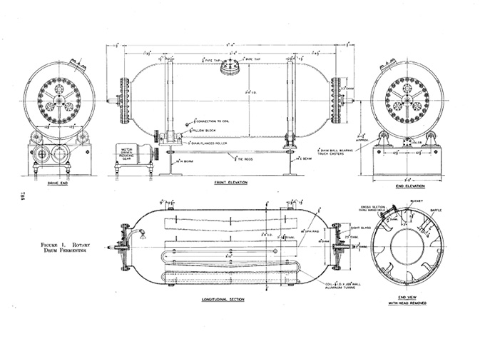
Fig. 19.2a Rotary drum fermenter (source: Gastrock 1938: 784)
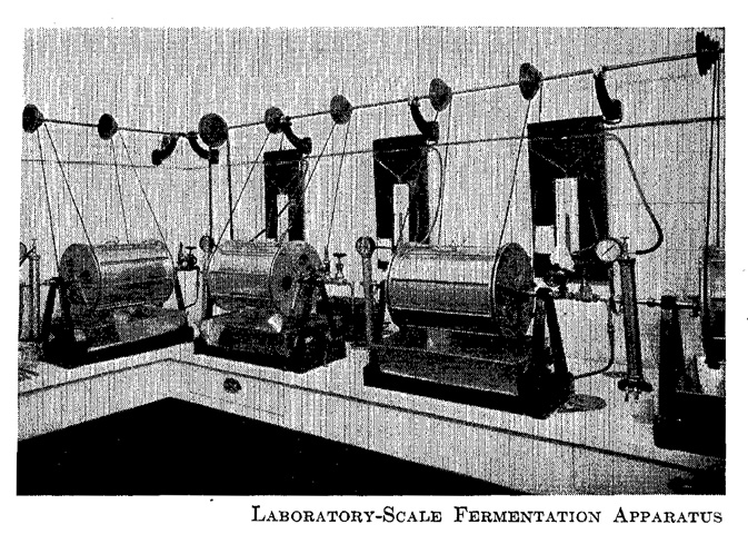
Fig. 19.2b Source: Gastrock 1938: 788

Fig. 19.2c Source: Gastrock 1938: 789
Creating a tank for aerobic fermentation with stirring addressed the problem of economy of space. In 1937, George T. de Becze and Alfred J. Liebmann employed an unusual stirred tank in three different yeast factories in central Europe. This iron-bodied tank was an upright cylinder. It had an outer layer that acted like an insulating jacket, where water of a fixed temperature would flow and regulate the temperature within the tank. An agitator was installed inside the tank in order to stir the culture fluid, to create contact between the fluid and air. The air was injected into the tank through pipes that had numerous pores, a process known as air sparging. A board placed on the inner wall of the tank acted to further disperse the air and mix the fluid. Because the culture fluid had a tendency to foam under these conditions, later stirred tanks brought anti-foaming agent into the fluid through an added supply pipe. This tank reduced the amount of compressed air needed to one fifth of the previous amount, and now two thirds of the tank could be filled with the culture medium, further speeding the fermentation process and raising the product concentration, since the microbial strains were distributed throughout the liquid. Submerged culture was also much more efficient than surface culture because the air bubbles allowed rapid supply of enzymes as well as rapid removal of waste gases. That said, the energy costs for this process were still high, since steam had to be made for temperature regulation and compressed air (Figures 19.3a, 19.3b, 19.3c, 19.3d).
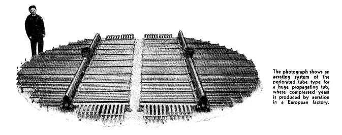
Fig. 19.3a Source: de Becze and Liebmann 1944: 882

Fig. 19.3b Source: de Becze and Liebmann 1944: 885
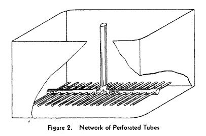
Fig. 19.3c Source: de Becze and Liebmann 1944: 885
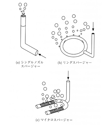
Fig. 19.3d Different kinds of spargers: a) single nozzle sparger, b) ring sparger, and c) micro sparger (source: Sakuma 2001: 488)
In the case of penicillin production, the technological bottleneck was not the problem of discovering a microbial strain that could produce penicillin, nor was it especially difficult to achieve bench-scale and small-scale penicillin production by surface culture. The bottleneck was being able to manufacture large enough quantities of penicillin cheaply enough to enable the drug to be used clinically among the general population, which scientists achieved only by using a stirred aerobic tank similar to the tank that de Becze and Liebmann used for yeast culture. In 1943, the penicillin tank had a capacity of fifty-four kilolitres. By 1955, penicillin tanks were about a hundred and twenty-five kilolitres in size, and by then the tanks were also beginning to make other antibiotics (Tanaka 2000). Eventually, the standard geometry of the tank settled at a cylinder with a depth of two to three times the width. The basic design of the stirred tank has changed little since then, although there have been innovations to the design of the agitator wing, for example, to better supply enzymes for yeast culturing or for high-viscosity culture fluids (which are common with fungal cultures) in order to distribute the shear exerted on the cells more evenly within the entire tank (Figure 19.4).
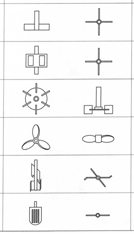
Fig. 19.4 Agitator wing designs (source: Sakuma 2001: 487)
Scaling Up
An industrial fermentation process begins with microbiological ideas and microbiologists’ work at the laboratory bench to culture the relevant strain and produce the desired chemical. For any fermentation process, therefore, the tank executing that process often takes the original form of a shake flask with a capacity of several millilitres to several litres. By a procedure of scale-up, the tank changes form from the shake flask to a jar fermenter (up to tens of litres), and leaving the bench involves a further scale-up from the jar fermenter to a pilot plant (up to several kilolitres), and finally from the pilot plant to a large-scale tank for industrial use (up to hundreds of kilolitres) (Figures 19.5 a–d).
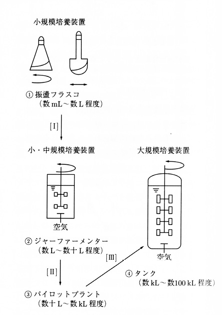
Fig. 19.5 Scaling up: (1) shake flasks (small-scale), (2) jar fermenter (small to medium-scale), (3) pilot plant (medium-scale), (4) tank (large-scale) (source: Takanaka 2001: 498)
A quantitative index is used to compare the environments and ensure that the production amount and production speed do not change as the culture environment increases in scale. In aerobic fermentation there are many indices one can use to measure changes: physical indices, such as the consumed power per unit fluid, or the Reynolds number of the fluid, or the average diameter of the air bubbles; or more physiological indices, such as the hydrodynamic stress exerted on the cells by the mixing, which can be measured by the flow of leaked biological materials from inside the cells. Engineers tend to select the parameters that are seen to be rate-limiting. For scale-up in penicillin production, common parameters used were the power consumed per unit of culture fluid, or oxygen transfer. Because scale-up details are commercial secrets, there is little available information about how this is done. But for penicillin, it is known that in 1954, Ernst Chain used a ten-litre jar fermenter in the laboratory, and ninety-litre and three hundred-litre pilot tanks in the industrial plant (Tanaka 2000).
Scaling up is a very difficult process, where engineers prepare for failure as much as for success. It can be especially difficult when using fungal cultures that generate viscous, non-Newtonian fluids, since in such cases it is more challenging to find a suitable parameter. When scaling up from the shake flask to the jar fermenter, the air supply method changes: in the former, outside air passes through a cotton plug into the culture environment, while the latter uses a sparger and agitator. This means that the air transfer to and from the cells, as well as the physical stress on the cells, changes. If either of these is a rate-limiting factor in the fermentation process, scale-up becomes difficult. The industrial tank is much larger than the pilot tank. It can be several storeys high (five to ten metres), such that instead of the homogenous environment in the pilot tank, there are gradients of gas concentration and pressure in the industrial tank. Scientists have developed laboratory equipment specifically for helping to research these elements of scale-up, such as a variable-pressure small-scale tank.
In the case of penicillin, industrialising the mould-based fermentation process therefore required chemical engineering expertise, beyond the microbiology and biochemistry that guided early bench-scale work. In Japan, the chemical engineer who was appointed by the Allied occupation government to lead pilot-tank construction in state-sponsored penicillin research, Ōyama Yoshitoshi, later complained that the Japanese microbiologists and biochemists showed less concern for mechanical issues than did the American microbiologist who was sent to Japan as a consultant on penicillin production.1 The Japanese submerged culture project began with a four hundred-litre pilot tank that eventually became a two-tonne tank. As is often the case for industrial processes, it was difficult for the researchers to get hold of engineering data.
The chemical engineers conceptualised the problems involved differently than the microbiologists and biochemists. To prevent contamination, microbiologists were accustomed to using cotton plugs and heating with gas fires. Extrapolating from such experiences, the microbiologists advised the chemical engineers that they should weld a cover onto the large-scale fermentation tank, and that they should apply a phenol seal wherever a flange was used in the culture tank. To the engineers, however, these suggestions seemed utterly misguided, and Ōyama later recounted feeling frustrated that the microbiologists could not clearly explain how much air flow was needed, or what the stirring power should be, or even what the purpose of stirring was (Ōyama 1969). Scientists knew that older alcohol and fermentation industries did use cotton plugs to filter out bacteria from the air supply, but what thickness should the plug be, for what rate of air transfer? Because there was no data available, the chemical engineers had to undertake their own research into these issues, and accordingly carried out studies on the air resistance as it passed through cotton, the mechanism of filtration of the bacteria, and so on.
The design of the tank itself was a cylinder made of mild steel, with an agitator inside to divide and disperse the air bubbles, and an opening for the air supply. It was a temperature-regulated environment maintained constantly at 24 ± 1 degree Celsius. To achieve this, in the smaller pilot tanks there was a second layer of wall, and in the industrial tank there was a built-in coil, through which water of the set temperature would be passed. The air needed to be supplied to the tank in a completely sterile condition. Thus, the air passed through a compressor and then through a raw cotton or glass fibre filtration machine before entering the tank, which was itself maintained at a slightly elevated pressure to discourage air from entering from the outside. An anti-foaming agent was added. The tank had an opening for inoculating the tank with microbial strains, an exit mouth where the culture fluid and air could be collected, and an observation window; all such parts that had contact with the outside air needed to be sterilised with steam.
Particular engineering challenges included the heterogeneity of the culture fluid within the multi-storey tank. There was the issue of how to get the air to behave as desired, and how to get the agitator to stir it effectively so that the bubbles were distributed throughout the culture fluid and had as much contact as possible with the cells. There was the question of how to prevent foaming. There was the problem of how to keep the tank operating at a fixed temperature for long durations. There were all the various things that needed to be accounted for to stop outside microbes from entering the tank. All these problems had to be overcome before penicillin could be cheaply mass-produced in Japan. In the immediate post-war years, hundreds of scientists and technicians at the bench and in industrial plants, in clinics and in companies, universities and other research institutes collaborated to make penicillin production work. Tank engineering was one key component of the endeavour.
Once a fermentation tank exists, it is in the company’s interests to keep the tank moving. A tank that sits idle is wasted. But each product has a life cycle after which it loses its market value. Antibiotics, the products that drove the fermentation tank boom, have an especially short life cycle due to antibiotic resistance. Other commercial products might become unprofitable or obsolete, or be driven out by new competition or regulation. Once a fermentation tank exists, researchers are compelled to think about a new product constantly.
A fermentation tank demands people for its survival. It needs people who can maintain and characterise microbes, who know which kinds of microbes and which kinds of products are likely to become interesting and profitable in the near future, who can screen microbes for an effective strain, who can develop culture media that are cheap and easily available in abundance, and who can work to deal with customer complaints. Much of this is bench-scale expertise. Then it needs people with the chemical engineering expertise to scale the process up to mass production and industrialise it, and to monitor and operate and maintain and repair the tank. It needs people who can develop an effective method for refining the chemical product, which relies on a supply of specific chemicals as well as specialised machines. Refinement is a separate process from tank construction, but it is a part of the fermentation process that similarly needs to be carefully engineered while keeping it a commercial secret. Moreover, the tank needs people who will work to develop uses for the by-products, and who will find economical ways to dispose of the waste.
As a box, a fermentation tank requires specialised scientific input in order to bring the tank and its associated fermentation processes into existence. The tank continues to demand the same kinds of scientific work, not only for maintenance and repairs, but each time the tank is called to make a new product to be brought to market. The fermentation tank determines what types of products can be made with it. When different kinds of products are introduced whose manufacturing processes do not quite fit the tank design (as in the case of penicillin fermentation) the design of the tank must be adjusted. The existence of the box is enabling – since it allows microbiologists to envision large-scale manufacture for a range of products that require similar fermentation processes – but also constraining – since when products are developed at the laboratory bench using different processes, the industrial tank environment must be altered for successful scale-up. This very tension between enabling and constraining compels innovation both at the bench and in the factory.
Notes
1 Ōyama speculated that this may have been because it was less common in Japan than in the US at the time for people to drive (and, therefore, operate and maintain), cars (Ōyama 1969:62).
References
de Becze, G., and A. J. Liebmann, ‘Aeration in the Production of Compressed Yeast’, Industrial & Engineering Chemistry, 36.10 (1944): 882–90.
Gastrock, E. A. et al., ‘Gluconic Acid Production on Pilot-Plant Scale: Effect of Variables on Production by Submerged Mold Growths’, Industrial & Engineering Chemistry, 30.7 (1938): 782–89.
Iijima T., Nihon no kagaku gijutsu—Kigyōshi ni miru sono kōzō (Chemical Technology in Japan—Structure from the Perspective of Business History) (Tokyo: Kōgyō chōsakai, 1981).
Ōyama Y., ‘Kagaku kōgaku no riteihyō—Kaken to penishirin puranto’ (Milestones in Chemical Engineering—Kaken and the Penicillin Plant), Shizen, 24.6 (1969): 60–67.
Sakuma H., ‘Hakkōsō’ (Fermenter), in Baioindasutorii kyōkai hakkō to taisha kenkyūkai, ed., Hakkō handobukku (Fermentation Handbook) (Tokyo: Kȳoritsu shuppan, 2001), pp. 485–90.
Tanaka H., ‘Hakkōsō, baiyō sōchi’ (Fermenters and Bioreactors), Seibutsu kōgakushi (Tokubetsu gō: Hakkō kōgaku 20 seiki no ayumi—Baiotekunorojii no genryū o tadoru) (Special Issue: History of Fermentation Engineering in the 20th Century—Following the Origins of Biotechnology) (December 2000): 24–32.
——, ‘Hakkō seisan no sukeeruappu’ (Scale-Up for Fermentative Production), in Baioindasutorii kyōkai hakkō to taisha kenkyūkai, ed., Hakkō handobukku (Fermentation Handbook) (Tokyo: Kȳoritsu shuppan, 2001), pp. 498–99.
Uchida S., ‘Penishirin to kagaku kōgaku’ (Penicillin and Chemical Engineering), Kagaku kikai, 12.1 (1948): 9–15.
Yoshida T., ‘Hakkō sōchi’ (Reactors for Fermentation), in Baioindasutorii kyōkai hakkō to taisha kenkyūkai, ed., Hakkō handobukku (Fermentation Handbook) (Tokyo: Kȳoritsu shuppan, 2001), pp. 491–95.